Sunday, 10 May 2026

Ressurection of a WirelessThings OpenPi (from kickstarter)

Many years ago, I was handed one of the openpi kickstarter devices (see https://www.kickstarter.com/projects/wirelessthings/openpi-wireless-computer-for-inventors-makers-and) after Ciseco/Wireless things had gone under and my former boss had no further use for it. The dinky keyboard (and USB dongle) was promptly snaffled by a (now retired) colleage, and I had a brief play with the board, realised it was a single core CM1 board and kinda filed it away.

I'd dug it out semi-recently to see if it could be pressed into service to run info-beamer down at the local men's shed, but I decided it probably wasn't worth the hassle and back into the box it went. Cue a spot of bench-clearing and I decided to see if it could run a current OS and work (I want some sort of RF bridge to get the RF blinds into Home Assistant and that may be a use case).

Notes which may help others in future. 

WirelessThings website is long gone (there are some snapshots on archive.org) but https://github.com/WirelessThings/OpenPi/ still exists and has the schematics. Grab em if you need them. 

The warning about not being able to connect to a CM1 with `rpiboot` from a mac still seems valid, but it worked great from the standard pi I have on my workbench. I grabbed the current 32 bit Pi Os lite from https://www.raspberrypi.com/software/operating-systems/ then dd'd it over to /dev/sda (the openpi has 4GB eMMC onboard) as documented at https://www.raspberrypi.com/documentation/computers/compute-module.html#flash-compute-module-emmc. There was some slight faffing as new raspbian/Pi OS images don't create the user or allow ssh in by default. Fixed up by touching the 'ssh' file while I had the image mounted on my desktop pi ("mount /dev/sda1 /mnt" for the boot partition, /dev/sda2 is the actual root volume) - I tried to be clever and edit the cloud-init files to get it to auto-update and pull my public keys from GitHub but it bombed out when loading the new video drivers. That was fixed by editing out the 

# Enable DRM VC4 V3D driver
#dtoverlay=vc4-kms-v3d
#max_framebuffers=2

section in config.txt and rebooting. 

I'm using a generic USB to ethernet (Realtek 8512) dongle rather than wifi, which got the device online fine, but I coun't ssh in even after adding my public keys to the pi (created by cloud-init) user. Turns out it helps if you don't have a shell of /usr/sbin/nologin.

I was hoping there'd be some magic would happen with the on-board eeprom to detect the hardware and set things up, but nope. You're going to need to edit the config.txt and at least add i2c and dtoverlay=i2c-rtc,ds1307 for the clock.

I grabbed the overlay dts from github and compiled (complete with warnings):

root@pi-cm1:~# dtc -o /boot/overlays/openpi.dtbo  openpi-overlay.dts
openpi-overlay.dts:47.17-27: Warning (reg_format): /fragment@2/__overlay__/spidev@0:reg: property has invalid length (4 bytes) (#address-cells == 2, #size-cells == 1)
openpi-overlay.dts:55.17-27: Warning (reg_format): /fragment@2/__overlay__/spidev@1:reg: property has invalid length (4 bytes) (#address-cells == 2, #size-cells == 1)
/boot/overlays/openpi.dtbo: Warning (pci_device_reg): Failed prerequisite 'reg_format'
/boot/overlays/openpi.dtbo: Warning (pci_device_bus_num): Failed prerequisite 'reg_format'
/boot/overlays/openpi.dtbo: Warning (simple_bus_reg): Failed prerequisite 'reg_format'
/boot/overlays/openpi.dtbo: Warning (i2c_bus_reg): Failed prerequisite 'reg_format'
/boot/overlays/openpi.dtbo: Warning (spi_bus_reg): Failed prerequisite 'reg_format'
openpi-overlay.dts:45.21-51.15: Warning (avoid_default_addr_size): /fragment@2/__overlay__/spidev@0: Relying on default #address-cells value
openpi-overlay.dts:45.21-51.15: Warning (avoid_default_addr_size): /fragment@2/__overlay__/spidev@0: Relying on default #size-cells value
openpi-overlay.dts:53.21-59.15: Warning (avoid_default_addr_size): /fragment@2/__overlay__/spidev@1: Relying on default #address-cells value
openpi-overlay.dts:53.21-59.15: Warning (avoid_default_addr_size): /fragment@2/__overlay__/spidev@1: Relying on default #size-cells value
/boot/overlays/openpi.dtbo: Warning (avoid_unnecessary_addr_size): Failed prerequisite 'avoid_default_addr_size'
/boot/overlays/openpi.dtbo: Warning (unique_unit_address): Failed prerequisite 'avoid_default_addr_size'

One reboot later (after enabling my overlay in config.txt) and it's not obviously better. 

Features this carrier is supposed to have:

SRF RF board

This was an in-house module by Ciseco (now defunct) - I suspect finding docs on this will be 'Fun' - No idea yet how to test it. 

Bluetooth LE 

Using a HM-10 module. Kickstarter updates indicates it may be on a second serial port as the only one visible at boot is
20201000.serial: ttyAMA0 at MMIO 0x20201000 (irq = 81, base_baud = 0) is a PL011 AXI 
 
Datasheet at https://people.ece.cornell.edu/land/courses/ece4760/PIC32/uart/HM10/DSD%20TECH%20HM-10%20datasheet.pdf 
ah gettingstarted has this note
dtoverlay=uart1,txd1_pin=40,rxd1_pin=41 

IR Receiver

i2c - LIRC config needed but config.txt suggests
dtoverlay=lirc-rpi,gpio_in_pin=35,gpio_out_pin=33

then complained about lirc-rpi being deprecated, so changed to 

dtoverlay=gpio-ir,gpio_pin=35

note on the schematic gpio33 is 'ir_out_nc' which ties in with there being no IR transmitter 

 Datasheet at https://www.vishay.com/docs/82496/tsop752w.pdf 

lirc package wanted to bring in hundreds of dependencies so not investigated more but this looks hopeful

[   57.886350] Registered IR keymap rc-rc6-mce
[   58.042885] IR RC6 protocol handler initialized
[   58.104101] rc rc0: gpio_ir_recv as /devices/platform/ir-receiver@23/rc/rc0
[   58.104738] rc rc0: lirc_dev: driver gpio_ir_recv registered at minor = 0, raw IR receiver, no transmitter
[   58.105325] input: gpio_ir_recv as /devices/platform/ir-receiver@23/rc/rc0/input3
[   60.170102] mc: Linux media interface: v0.10
 

RTC

nice and simple
dtoverlay=i2c-rtc,ds1307
(I haven't fitted a battery so still dependent on chrony to set clock)
 
[   78.005555] rtc-ds1307 1-0068: registered as rtc0
[   78.033781] rtc-ds1307 1-0068: setting system clock to 2026-05-10T13:12:38 UTC (1778418758)  

Temp sensor

i2c based https://www.ti.com/lit/ds/symlink/tmp100.pdf
apparently in the kernel under lm75 hwmon driver
https://git.kernel.org/pub/scm/linux/kernel/git/stable/linux.git/tree/drivers/hwmon/lm75.c?h=v6.12.87
however adding dtoverlay=i2c-sensor,lm75 to config.txt and rebooting isn't working:

[ 76.812881] lm75 1-004f: supply vs not found, using dummy regulator
[ 77.016199] lm75 1-004f: probe with driver lm75 failed with error -121 

Then I noticed the schematic has both add0 and add1 tied to ground, so address is 0x48 - one quick bodge to the config.txt

dtoverlay=i2c-sensor,lm75,lm75addr=0x48 (possibly a straight addr=0x48 would work too?)

reboot and looking good

[   77.814608] lm75 1-0048: supply vs not found, using dummy regulator
[   77.864130] hwmon hwmon2: temp1_input not attached to any thermal zone
[   77.864210] lm75 1-0048: hwmon2: sensor 'lm75'
 

andrew@pi-cm1:~ $ cat /sys/class/hwmon/hwmon2/name
lm75
andrew@pi-cm1:~ $ cat /sys/class/hwmon/hwmon2/temp1_input
22500
andrew@pi-cm1:~ $


GPIO Button


HAT EEPROM


GPIO Headers on the underside 

That's a future project :-) 
 
.. to be continued 


Thursday, 25 December 2025

Energy metering update

 This is an update to my previous post (https://blog.elwell.au/2024/09/tomznhiking-dds238-2-rs485-energy-meter.html) as I've swapped out the bulky wemos + separate RS485 module for a din-rail ready waveshare esp32-s3 based device (see https://www.waveshare.com/ESP32-S3-RS485-CAN.htm) which looks much better and can even go in the switchboard. It takes 7-36v supply voltage so any of the mean well din PSUs work well depending what else is required.

Anyway, my git repo (https://github.com/Elwell/ESPHome-DDS238) has a new branch (esp8266) for the legacy hardware - updated slightly as I'd omitted the 'state_class' previously and it wasn't working with the new energy dashboard - and the new hardware is in the 'main' branch.

Wednesday, 12 February 2025

Too many buttons

 I have a standard ham licence (VK7HPC) and am currently poking at a Retevis RT95 (same as the Anytone AT-778UV). As I'd like to use it for digital modes, Steve (KM9G) over at Temporarily Offline Ham Radio has a playlist where he's investigating the pinout to make a microcontroller APRS interface, however he's not yet mentioned how to memory jump or enter a direct VFO frequency. Sure CAT control would be nice, but this radio's under 200 AUD delivered, so that's unlikely to happen. 

So, the manual hints at "keypad serial data" on pin8 so with a bodge together of 2 cat5 outlets, some wire and a logic analyser, lets see what we can find...


Force of habit means I used the T568A colours, so the from the pinout shown here you'll need to swap the orange/green pairs round. 

Anyway: Up, Down, PTT all get pulled to ground when pressed as expected and there IS some serial data on pin8, now I need to sample and collect more...


Update

In a stroke of good fortune, it appears to be plain ascii at 9600 baud. Pressing each key in turn spat out AL~K1, AL~K2, ... AL~Kx where x is 0-9,*,#,A-D and / (the latter being the toggle for A/B input)

Next up will be introducing it to little bobby microphone and seeing if I can send commands to the radio directly from a microprocessor


Friday, 31 January 2025

Particulate measurements near bushfires

Back in the 2019 Tasmanian bushfires we were lucky enough to be the other side of the Huon River from the fireground,  however we had a LOT of smoke (compare the photo below to the street view image)

Smoke filled landscape
We were also lucky enough to take part in a Huon Valley trial to compare HEPA filter systems which used a pair of CSIRO Smoke Observation Gadgets (further details on these units in Sensors 2021, 21(21), 7206; https://doi.org/10.3390/s21217206) to log the air quality (pm2.5 and pm10 measurements) inside and out. 

It's now 2025, and while we've been very lucky compared to the US and mainland Australia, we now have a bushfire nearby (~6km from our house) that contains the following advice:
Residents should be aware that smoke and ash may be visible in the Channel area over the coming weeks, and anyone who is at higher risk from smoke should enact their personal health plans.
So, it's time to DIY some new smoke sensors! (I would just rely on the excellent BLANkET network already in place in Tasmania, but there aren't any downwind of the current fire)

Hardware

I already have a pair of PMS7003 sensors unused in a 'future projects' box, so we'll use them. They are supported by esphome, so using an esp32/esp8266 with them seems a simple choice

Mine (located in Kettering) will use a wired esp32 (because POE makes that simple), and I'll see if I can get one mounted at the Channel Men's Shed in Margate which will need to use wifi

I don't have a nice shiny 3d printed enclosure, so it'l use something like an old yoghurt tub to weatherproof them.

Build

.. To Be Continued at the weekend :-)

Monday, 4 November 2024

Word of mouth Skye History

Many years ago we lived in the Old Manse in Waternish, Skye. If you look on the maps, you'll spot that unlike nearly all the other houses on the road, the Manse has house *directly* opposite, blocking the view over Loch Bay and the Minch. See also street view

The backstory to all of this is that the Minister at the time had fallen out with the Factor / Laird and when the health board were looking to build a 'nurses bungalow' the only land available in the entire area was that plot, directly in front of the Manse.

As with all the best tales, the twist was that when the factor became old and decrepit, the only person who'd take him in was ... the minister, so he spent his final days looking out at the non-view.

(blogged as a response to https://www.youtube.com/watch?v=p8fOJdmSbdU)

Monday, 23 September 2024

Tomzn/hiking DDS238-2 rs485 Energy Meter with ESPHome for Home Assistant

There seem to be several branded versions of this cheap 2 unit wide energy meter available online from the regular stores. I have a 'tomzn' branded on purchased several years ago and monitored the shed power in our last house. It's been relocated to the new place and is now in the switchboard in the shed^Wart studio in the garden.

Interfacing to home-asisstant

There are a pair of RS485 terminals and second pair provide pulse output. I got the sparky to run a short length of RS485 cable to a convenient location near a GPO for a USB power supply. I then have this connected to a cheap MAX485 module and on to an ESP8266 using the hardware serial port pins. I'm driving the max485 breakout with 3.3v so I don't need to worry about level shifters.

It's using a full-size Wemos D1 R2, purely because that's what I had on hand. As I'm using the serial port pins for connection to the RS485 converter, unplug before serial flashing. (OTA updates are fine)

My current software polls the meter every 5 seconds (note the RX/TX leds lit on the breakout, and the phone symbol on the meter LCD when this happens) https://github.com/Elwell/ESPHome-DDS238 has a very similar config to production

and you end up with this on the esphome and home assisstanr web interfaces


Friday, 19 July 2024

New House, New Blogpost

 Well, it's been a while since I last posted an update - shorter snippets are likely to be on Mastodon (https://mast.hpc.social/@Elwell) so figured I'd scribble something down.

We sold The Roundhouses in Sept 2023 and have moved "Over East" to Kettering. Now that I have loads of spare time (ha ha ha ha) I've joined the local Mens Shed which has an active ham group (VK7CMS). This and a discussion on the REAST discord about packet /APRS got me thinking about how to packetiffy a foxhunt. First thoughts scribbled at https://github.com/Elwell/ham-geocache

Tuesday, 15 March 2022

Feeling Pumped!

Having just had a day without power, and then going round the site to check everything came back online correctly (including services such as water pumps, septic systems, freezers etc) I started thinking again about our wastewater system. 

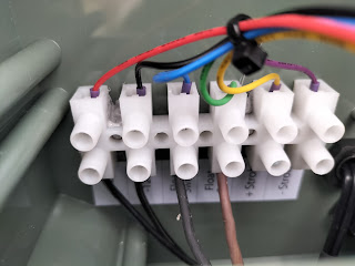
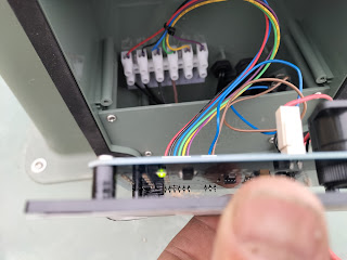
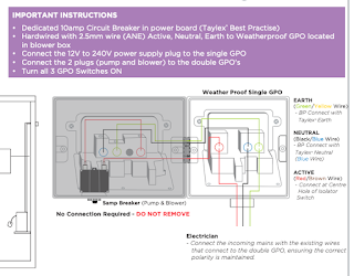
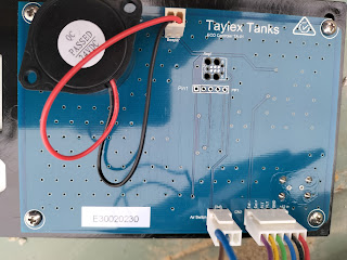
This is a Taylex envirocycle (septic tank + air blower + submersible pump in the final stage to deliver the effluent to 200m+ of dripper lines in a field). The "smarts" aren't really much - The power from the main switchboard comes in to a single outlet that has a 12v plugpack that powers the PCB, and on to a double outlet (with an overload trip) that powers an air blower + submersible pump. The blower runs 24/7 and has a pressure switch going to the PCB, and the pump cycles independently when it's float switch rises. There's a high-level float switch that triggers an alarm on the PCB, and that's about it.


Wishlist

Something that integrates with Home Assistant and tells me:

  • system power OK
  • Binary sensor for Air pressure trip
  • Binary sensor for high level alarm
  • Indication of when the discharge pump's running
All bar the last of these can be picked up from cabling already coming into the "controls" housing, but there's no way the existing system can pick up the pump-run sense. As all the pump cabling is pre-terminated I'd like to leave it that way, and I suspect the simplest method is to add a CT clamp over the active (live) cable in the double socket but that's likely to be very space constrained as there's also a circuit breaker in there. The plugpack is a switched mode DC one, so no clever voltage measurement at the same time to get accurate usage


Design

I think the best way would be to replicate the existing PCB (dimensions, pinouts, LED / mute placement) but add in something like an ESP8266 that can sit on our telemetry wifi network (signal strength down by the septic tank is good) and there's already plenty of options for integration (tasmota's trivial to customise)

This should keep me out of mischief for a while, as well as maybe being that "I should really learn KiCad" itch.

Concerns


The obvious one is what about updates? ANY network connected device presents an attack surface if not maintained. Sure, I'm likely to keep stuff ticking over, but what about $future_owners? obvs, I won't be using a cloud service for any of this and hardware will be 'input only' so it won't affect the running of the system. What's the design lifetime for one of these units anyway? 20-30 years?
There's also the thorny issue of Certification - a one-off's going to be horrifically expensive to get any sort of certification for, and who'd install it? As Taylex's website states Please remember that by law, only licensed professionals are permitted to service and maintain on-site wastewater treatment systems.
Sigh. I suspect this may remain a pipe dream.

Wednesday, 2 September 2020

Thoughts on Statuspage.io integrations

 $dayjob uses statuspage.io for our public status page. Although I've got some things automated, there's still a bunch of components that need manual updating when there's an issue (enough to keep me out of mischief working out how to automate them without false alerts anyway). However this post isn't for getting info _in_ to statuspage, but for how to get it _out_, and what I want.

We're predominantly a command line shop (no, we don't yet have a JupyterHub frontend), so users are presented with a MOTD on login. Now, wouldn't it be good if that could be updated automatically with details of upcoming planned outages as well as any recent (and current) incidents that affected the service you're currently logged into?

So - Armed with the API, it should be possible to get upcoming maintenance[✓] and the impacted components[✓], but where do I map the cluster name to the statuspage group_id? or, for that matter any of the autogenerated id strings. Hard coding them into scripts is out, a lookup makes sense but how many CMDBs out there come with that sorta functionality built in. and we're back to another 'where is my source of truth?' problem. Sure I can string match components->name and check that "group": true and then pull the ID, but... yeah faffy. 

Anyway, after much parsing (all hail requests) it's possible to get the various incidents/component states/planned maintenance out and the resulting text snippets touched to the correct updated_at timestamp whereupon they can be pulled into the final output whenever the files are regenerated by a Makefile build under Jenkins. The goal of DRY is starting to be achieved by updating one place (currently statuspage) and having that trigger a build via webhook which then distributes the info out to the clusters.

I think a former colleague summed it up fairly well tho.


Thursday, 2 April 2020

Solar off-grid cabin

We have a small cabin on the site that used to have a 200w panel, 65Ah deep cycle lead acid battery, el-cheapo PWM charger to power some LED strip when we visited.

While this was OK for occasional use, there's no way it'd be any good for regular usage, let alone constant 12v fan for the composting loo, water pump, fridge, wifi etc. So, time for an upgrade.

First off, new panels. The roof faces pretty much north with not much shading. Jaycar sells a fairly decent range of rails and clamps, and I purchased 3*300w (seemed to be the sweet spot for size/cost/output) panels from ebay that were 800mm wide to fit on a 2560mm rail. 

Wired in series, they still fall under the wiring rules definition of 'Extra Low Voltage' (< 120v ripple free DC). Even on the sunniest of days I've only seen them putting out about 70v so far.

Batteries. The performance benefit of LiFePO4 is huge compared to lead-acid. I took a chance and purchased a set of 8*123 Ah cells from AliExpress ("BLS Official Store"). These came in at 778 USD delivered, nicely packaged and all 8 cells were within 0.02v of each other when I checked.
For protection / balancing I purchased a 'Daly' 8s BMS with a common port (again, AliExpress), and a 120A isolator from Jaycar. To keep cable runs as short as reasonably possible and not clutter up the limited space in the cabin, I decided to put the batteries in a lockable toolchest (bunnings) fixed to the supports for the bathroom shed. There's a small condensation drain in the corner, and the batteries themselves are raised from the base slightly with some strips of yellowtongue. My one gripe about this is the cables on the BMS are slightly too short to position a the BMS neatly.

Linking the two together is a fairly chunky charge controller - I went for a 50A EPEVER Tracer, mainly because they seemed to have a good reputation for the price, and published specs for the modbus-rs485 output. Once you go to the 50-100A level range of controllers, the load connections aren't on the charge controller, but need to be taken off the battery itself. There are a couple of switched outputs that can be used for LV disconnect and/or external charging relays. Oh, and it's a little larger than the old one we had.

Back to ebay for a switchboard and some DC rated MCBs (electric_super) to try and get a neat job. I've got plenty of space behind the melamine chipboard panel for the terminal posts (battery incomers), LV disconnect relay and a POE injector for the wifi access point

My plan is to have remote telemetry back to home-assistant / grafana long term, but for now I've put an 'MT50' meter into the cabin (with only moderate swearing for the cable run) 

So, what next?
I'd like to run an inverter occasionally, but am not convinced we have enough capacity in the batteries (it'd be used to run things like a vacuum cleaner). Today was heavily overcast and the bms dropped the batteries with LV protection, so perhaps an option to connect a charger (this would mean a lot of extension leads or a genset) - potentially one of the combined units? depends on wiring regs if its "fixed wiring"

Getting the telemetry off is becoming more important now we're approaching winter. I've discovered I can't use the wired tail on the UAP-AC-M when it's operating in 'wireless uplink' mode or it thinks its uplink is on the wired side and keeps disconnecting from its upstream partner. So, I'm looking for a low-power wifi SBC that'll easily let me script up modbus monitoring from the tracer, water usage from an impeller sensor, and the water tank volume from an ultrasonic sensor, and fling the whole lot at the on-site MQTT broker.

Inside? well I've added some upstairs lights, multiple DC-DC converters so there's places to charge a mobile phone, and some better kitchen lighting. As well as the fridge and waterpump (we now have both cold AND HOT running water)


Monday, 12 November 2018

Garden Irrigation, Pt 1

Some more background to my 'home assistant powered irrigation system' -- I'll write up a couple more articles as build progresses - I'm still waiting on some critical parts to arrive, like PVC pipe fittings and an Arduino Mega.

The Grand Plan.
The 2 main garden bed areas need to be automatically watered. The small 'hexagon' area contains 6 raised beds and a small central area. The main veggie patch (still being built. slow progress...) is around 20 beds. Later automation will include more smarts (hooking in my rainfall sensor, some buried gypsum sensors and soil temperature monitoring), but for now, the priority is to save on the 30-60 mins with a hosepipe in the evenings. Oh, and we're on tank (rainwater collection) water, so wastage is bad mmmkay.


The irrigation units themselves won't be 'smart' - All they need to do is send valve (relay) status, and respond to controls. I have an internal MQTT message broker, so a basic arduino + ethernet shield + 8 channel relay board does the small bed, and an arduino mega + ethernet (or an ethermega) + 3 8 channel relay shields the main veggie patch.

Sample arduino code is available on GitHub, (functions? who needs functions...) and yeah, it's not elegant. While it follows the syntax for the home assistant MQTT switch device, some of the defaults aren't the same, so I need to explictitly set them for now in the hass config. such as

switch:
  - platform: mqtt
    name: Hexagon bed 1
    icon: mdi:water
    availability_topic: status/hexIrrigation
    command_topic: control/hexIrrigation/valve1
    payload_on: "1"
    payload_off: "0"
    state_topic: status/hexIrrigation/valve1
    state_on: "On"
    state_off: "Off"

You can see here that I use status/hexIrrigation as LWT (so I know if the controllers on/offline) as well as the the relay state. I'm only using retain on the LWT, not the valves themselves. Power cycling the unit will (should!) reset back to all solenoids off, but I don't yet check and publish this, so hass may get confused if it loses comms. "Fixed in the next release" apparently :-)

I also want to integrate a flow sensor into each unit if possible (suspect I'm running out of digital IO on the small unit) to get an overall volume of water that's gone into the garden - fed, as normal into grafana.

I'll throw in another couple of postings (with pics) as the build progresses. but today I had an audience while working on the fence... (it will be fully netted to keep out the possums, pademelons and our hens)


Thursday, 1 November 2018

Measuring empy space

If you've been following my recent posts on twitter, you'll be aware that I've finally got round to hooking up the MaxBotix rangefinders into our water tanks. So far I've done the main house tank and have sketches and buried duct ready to do the ones that water the garden.

Some more technical details here than I can fit in tweets:
* The sensors themselves sit through the roof of the tank. This involves drilling a 3/4" hole in the top of the tank and inserting the sensor from below, so you won't want to put it more than an arms reach from the access hole. The sensors I purchased have NPR thereads not BSP, so you may want to pick up matching nuts at the same time depending on local availability.
* I mounted some 6-way header pins on the sensor, and soldered the female end onto the cable so that it didn't twist as I tightened it up. All mounted in a 20mm conduit box on the tank.


Inside the shed, I'm just using a clone arduino with a wiznet ethernet shield (ebay/aliexpress) and a very basic sketch using the pulse width measurement from the sensor. As normal, it's available on GitHub for anyone interested. It pushes to an on-site MQTT broker (mosquitto) that's used to gather various sensor metrics and fed into home-assistant, where it also gets archived into InfluxDB for longer term plots

status/housetanksensor online
sensors/housetanks/depthbelowsensor 419
sensors/housetanks/litres 20762

I use the status for LWT messages, and the sensors has the raw air-gap measurement (mm below sensor - range is 300 -> 5000) as well as a calculated volume (see the arduino code for constants and calculation)

Importing into hass is as simple as
  - platform: mqtt
    name: House water tanks volume
    icon: mdi:water-pump
    availability_topic: status/housetanksensor
    unit_of_measurement: l
    state_topic: sensors/housetanks/litres
into the configuration.yaml


Next up, getting the irrigation system working...

Thursday, 14 June 2018

Overlaying SLURM job timings on Grafana plots

As you may have noticed, I'm quite fond of Grafana and use it at home and work. One of the dashboards I have at work is the general state of our lustre filesystems, showing IO and metadata traffic, collected by a custom python script (I'm working on converting this to a real collectd python plugin) which stores the data in an influxDB.

I've since written a small python script that talks to our SLURM accounting DB, so that given a jobID, we can get the start/end times and overlay those using the annotations API. One minor niggle in that the API expects epoch milliseconds, and seems to be tied to the TZ of the browser that generated the API key.

however...
~$ annotate_job 2924399
Found the following job:
  User: bskjerven (pawsey0001)
  Cluster: magnus, Partition: workq, QOS: normal
  Nodes: 768, CPUs: 36864
  Start: 2018-06-11 17:23:22, End: 2018-06-11 19:54:44
Got something back - Annotate? (y/n) y
200 - Annotation added

and lo - 


Friday, 23 March 2018

weewx to home-assistant

At home I have a Fine Offset (this one branded by Jaycar) weather station that publishes to weather.two-fifteen.com via weewx (this is much simpler now I don't have to have the thing solar mounted in a field using a 3G dongle - at least the NBN is useful for some things) but I'd like to be able to use some of the measurements in home-assistant.

There isn't yet a direct plugin (spare time project anyone?) that I can see, but because I'm pushing the metrics locally to influxdb (have I mentioned I like drawing graphs of things?) for grafana, it's possible to use this in home-assistant via weewx-influx

Weewx config:
[StdRESTful]
      [[Influx]]
        host = localhost
        database = weather
        unit_system = METRIC

and on the home-assistant server:
  - platform: influxdb
    host:    203.0.113.88
    queries:
    - name: Outside Temp
      database: weather
      measurement: 'record'
      field: 'outTemp_C'
      group_function: last
      where: 'time > now() - 5m'
      unit_of_measurement: °C
      value_template: '{{ value | round(1) }}'

and lo and behold, you should end up with something like this:
which when compared to our nearest BOM observation site up the road in Grove correlates nicely (Grove is in a valley, we're at the top of a hill)


Tuesday, 16 January 2018

Don't count your chickens...

We have a cheapo Chinese incubator for hatching eggs. According to popular Internet postings, the calibration of the 'temperature setting' on the front vs reality inside isn't terribly accurate. Since I have a stack of 'Ruuvitags' (https://ruuvi.com) from their kickstarter, I decided to put combine them with Grafana so I could start logging the data and plotting trends.

First up, by default they broadcast an Eddystone beacon, so that you can simply see the data on a phone / tablet (via the Physical Web), however with Google dropping this feature, I decided to switch them to Raw mode which has a higher accuracy. This is done by simply opening the tag and pressing the 'B' button to toggle between Raw (LED blinks red) and URL (LED blinks green) mode.

I'm using a Raspberry Pi 3 as a Bluetooth receiver. Running Rasbian 9 (stretch) means that I get a recent (v 5.43) version of bluez which understands BLE. Although there's a Java app to push to influxdb, I'd rather use Python, so pip-installed the ruuvitag_sensor package.

Initially this worked 'OK', but the logs were full of noise on the listener, so I hacked up a quick script based loosely on the examples. When done, it was much cleaner than the original and was picking up more of the broadcasts.

Once again, trivial to add to influx with some templating

Tuesday, 10 October 2017

Plotting Lustre MDS stats

At $dayjob we have several large filesystems - for example our /scratch system has 3.1 PB of space using over 1000 HDDs. Although each vendor offers their own dashboard for monitoring they're all a little bit crap and don't integrate with anything else.

Cue an afternoon setting up influxdb (trivial) and grafana (also trivial) on a spare VM and a simple python script run on the metadata servers:

[admin@snx11038n003 ~]$ cat push_mdt_stats.py
#!/usr/local/bin/python2.7
import urllib
import time

def grabbit(mds):
 post = ""
 with open(('/proc/fs/lustre/mdt/%s/md_stats' % mds), 'r') as f:
    for line in f:
        k,v,null = line.split(None,2)
        if k == "snapshot_time":
            ts=int(float(v)*1000000)
        else:
            post += 'metadata,fs={3} {0}={1} {2}\n'.format(k,v,ts,mds)
 with open(('/proc/fs/lustre/mdd/%s/changelog_users' % mds), 'r') as f:
    tmp = f.read().split()
    # we can cheat here as they have the same format - 3rd item in list is current changelog count, and then
    # from the 6th item on we get changelog id / position to pull into a dict
    head = int(tmp[2])
    clog = dict(zip(tmp[5:][0::2], tmp[5:][1::2]))
    post += 'changelog,fs={2} head={0} {1}\n'.format(head,ts,mds)
    for cl,count in clog.items():
        post += 'changelog,fs={3} {0}={1} {2}\n'.format(cl,count,ts,mds)

 post=post.encode('ascii')
 p = urllib.urlopen('http://influxbox:8086/write?db=lustre&precision=u',post)
 #print(p.getcode())

while True:
  try:
    grabbit('snx11038-MDT0000')
  except:
    sys.exit("Whoa, that went a bit Pete Tong!")
  time.sleep(10)

And a couple of clicks in Grafana can soon knock up a dashboard:


Tuesday, 29 August 2017

PSU tinkering, Part 1

As previously blogged, I've got a couple of 12v 88.7A PSUs that I'm trying to control under arduino. Stage 1 complete - It powers up with a trivial bit of code

/* Arduino control for (ex) server PSU 
 * Andrew Elwell <andrew.elwell@gmail.com> August 2016
 * Released under BSD licence
 */

 /* Controls / Pins based on data sheet available at 
  *  https://belfuse.com/resources/PowerSolutions/SFP1050/bcd20031_ab_sfp1050-12bg.pdf
  *  
  *  A6/B4/C4/D4         +3.3 standby (power to arduino)
  *  A3/B1/B3/C1/C3/D3   Return 
  *  B5(SDA) / C5(SCL)   I2C
  *  B6                  Bring low for PS ON
  *  C6                  AC OK (if high)
  *  D6                  PWR OK (if high)
  *  
  */


#include <wire.h>

int ACOK  = 2;
int PSON  = 3;
int PWROK = 4;
int LED   = 13;

void setup() {
  Wire.begin();                // join i2c bus (address optional for master)
  pinMode(ACOK, INPUT);
  pinMode(PSON, OUTPUT);
  pinMode(PWROK, INPUT);
  pinMode(LED,  INPUT);
  
  digitalWrite(PSON,HIGH) ;   // Stay off until ready
}

void loop() {
  if (digitalRead(ACOK) == HIGH) {
    digitalWrite(PSON,LOW) ;
  } 
  if (digitalRead(PWROK) == HIGH) {
    digitalWrite(LED,HIGH) ;
  } 
}

The one gotcha that I needed to get it working was to also bring PS A0 low (I2C address) and suddenly green led and 12v out!


Tuesday, 4 July 2017

I've got the power

(It's getting, it's getting, it's getting kinda hectic)

So, another "I should really get round to that" project that's worked its way to the top of the desk is repurposing a skip-dived server PSU (or 4) to be more usable.

Exhibit A - One ex-sun 'SPASUNM-03G' PSU, which spits out a fairly chunky 12v at 86.7A
Since these were pulled from a bunch of servers, the output is a less than friendly set of three paired contacts for +12 and another set of three pairs or the ground. It won't start spitting out 12v when you plug a mains lead in as it needs the PS_ON connector bringing low. Power-one seem to gave been bought out by bel, and the datasheet is available here.


Rather than the (sometimes) crude way people have modified these and similar server PSUs over at RC Groups, I thought I'd hook up an arduino and be "smart"

So - Grand Plan (TM)
* Nice big illuminated push button for on/standby
* LCD display to show status (output / alarms / temp)
* No screaming 'fan-at-maximum' setting all the time

This shouldn't be that hard, right? Arduinos can do i2c and I have a bunch of 3.3v ones to hand, so I can drive this off the stby 3.3v (even that's at 3A on this thing)

TO THE SOLDERING IRON! ... to be continued


Sunday, 25 June 2017

Handheld animal RFID reader teardown

As some of you may know, we have a small herd of llamas and although each is easily recognisable legislation and the Llama Association of Australasia Inc. require that the animals be microchipped. As a geek, I'd also like to integrate routine monitoring of weight, so my idea is to use the embedded microchips (same as your pet FDX-B 'grain of rice' thing) to save the scale output into the relevant animal record (yup, another use of a Raspberry Pi in the steading)

Aliexpress provided the reader, and 5 small screws later (and another 2 for the PCB) has the innards exposed at https://www.flickr.com/photos/elwell/albums/72157683149501201

Sunday, 24 July 2016

The writing's on the wall

For the last couple of jobs I've had, having some sort of status display has proved itself really useful. Things like an overloaded nagios dashboard help to drill down to see what system issues you may have, but on large systems there'll always be some component that's not green (however your service should work around these transparently to the end user).  In a smaller team without 24/7 operations staff and shift handovers, how do you know things aren't on fire when you walk into the office? - I'll ignore the fact that you probably read your email over breakfast.

Concerto

At $job[-1] we put a spare monitor on the office wall and ran concerto on a PC feeding it. The backend at that time was php, and made assumptions such as assuming that short tags were OK - I hacked on a branch to make it more standard with the scientific linux systems we were using at the time. Given this was (is?) a student project out of the Rensselaer Institute ir's hardly suprising as young developers want LATEST SHINY. They then went through a second system effect, rewriting from scratch and completely missing the launch of the raspberry pi, which could have made a killer combination.
The problem is that many browser based clients need the overhead of X11 and all the various hacks to remove mouse cursors and make them more 'kiosky'

info-beamer

Fast forwards a few years and I have mini-magnus on my desk showing status and a set of 3 unused monitors on a wall looking to display some info. A quick bit of research flagged up info-beamer which has been used in production at the CCC events for several years. I've been playing with it for a couple of days now in the standalone pi and hosted variant.

hosted info-beamer

The install of this is very smoothly done. Small zip file download to populate an SD card with the raspberry pi bootloader files and a squashfs  and it self-installs the rest of the distribution from S3 and prompts you to register the node to your info-beamer account (in a similar way to a chromecast).
Florian has made some really nice touches to the setup - little things like setting cec_osd_name if your TV screen uses it, a custom kernel logo, and suppression of all but the player-related boot messages. In a public area, this makes it look a lot more professional than most of the other solutions which show the operating system before launching a player should they reboot. I've only played with a couple of the sample packages, but the install process is slick, if initially confusing terminology between packages, setups and playlists.


I'd love to see this integrated with indico - the meeting software used at CERN. Hint :-)

standalone info-beamer

The personal use player is distributed as a binary executable - I can understand the reasons for that, but it doesn't feel right. It doesn't (yet?) come as a debian package - It should be trivial for me to do myself according to the docs. When that's done, I'll install and run using systemd rather than the daemontools method (which is used by the various syncer scripts used in the hosted version). My concern is that the logging is presently noisy (good for debugging, bad for SD lifetime) 
I'm also planning on managing these R-Pi nodes using Ansible (Puppet is overkill for this as I want something that can bootstrap up a fresh SD card without needing extra daemons running) so I suspect there'll be future blogging on that. 

I've not yet investigated sending values directly to the info-beamer listening port (hoping I can do something with an MQTT subscriber) but pushing json files from various subsystems seems to work well. Obligatory screenshot:
Prototype display testing
Overall, I'm very impressed. Given I'd started learning lua for some nodemcu work I should be able to develop something functional. I've asked the work graphic designer to assist, so hopefully it won't end up "engineer style"

Ressurection of a WirelessThings OpenPi (from kickstarter)

Many years ago, I was handed one of the openpi kickstarter devices (see https://www.kickstarter.com/projects/wirelessthings/openpi-wireless-...